DIY Piezo-Electric High-Sensitivity Touch Probe

I built this mechanical piezo-electric touch probe recently as an extension to a CNC machine to sense the depth of surfaces. It works with the grbl CNC controller and probably others.
The goal was to flip a TTL (5V) signal whenever the probe was touching a surface mechanically. Unlike classical mechanical switches which have moving parts, this probe is ‘solid state’ and must emit a signal as early as possible when there is mechanical contact, even when the probe is touched ever so slightly, and even on non-conducting materials.
The idea of piezoceramic touch probes is not new. They are based on the bending of piezo ceramic, which is constructed behind the surface of the probe. The benefit of using a piezo touch switch is its ability to interact with surfaces of virtually any type of material.
The cheapest professional touch probes cost several hundred Euros, and upwards. That was out of the question for my purposes. However, with a bit of ingenuity, I managed to construct a probe from scrap metal and electronic parts that cost less than 10 euros.
The heart of the sensor is a piecoceramic loudspeaker/beeper. However, it also can act as a “microphone”. When the piezoceramic surface is deformed mechanically (either via sound or by direct pressure), voltage is generated (up to 2 or 3 Volt).
The tricky part is that upon pressing, charge is generated, which dissipates quickly via the piecoceramic material itself. This means that upon releasing the mechanical pressure, charge of the opposite sign is generated. This negative voltage is a problem: One cannot simply feed this signal into a TTL-level microcontroller (µC) without risk of damaging it. Also, slight touches would only generate Millivolts, below the threshold voltage of a µC pin. So, electronics have to be made that act as an analog-to-digital converter. Specifically, I implemented an inverting Schmitt-Trigger (see below).
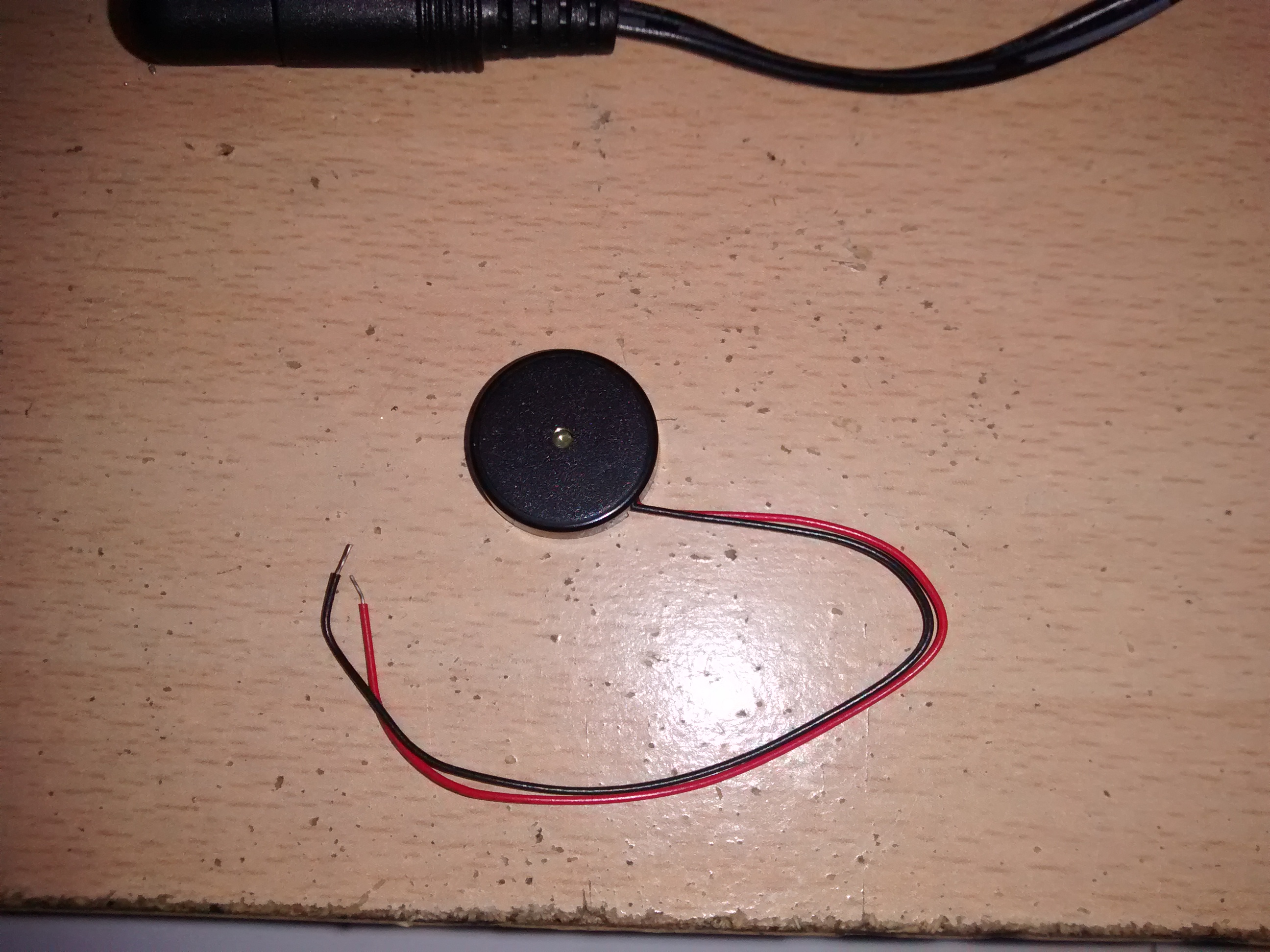
Here is the piecoceramic loudspeaker/beeper that I used (it cost less than 1 Euro):
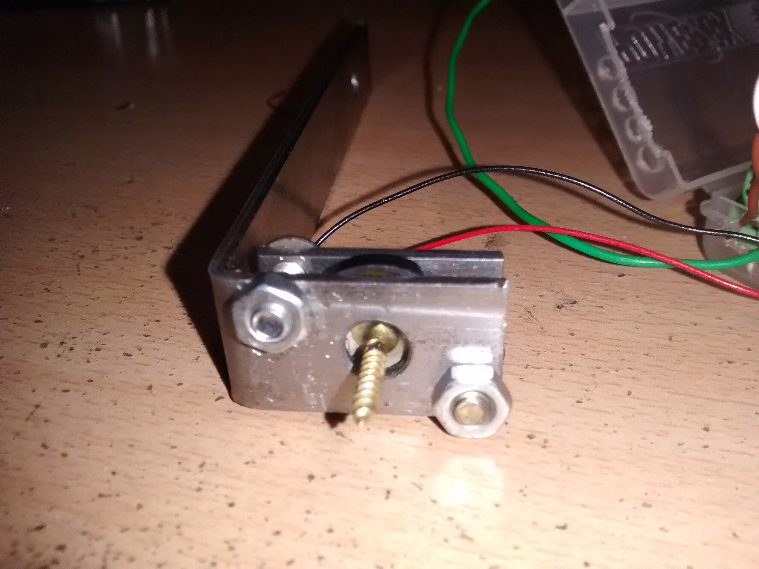
I simply removed the plastic back plate from the beeper to expose the piezoceramic element, and, in its center, glued a short wood screw on it with a bit of epoxy glue.Then I bent some metal and drilled some holes to create a stable holder for the beeper (this will be mounted directly on the CNC machine). The nice feature about this particular beeper is that the piezoceramic element is suspended by its plastic packaging, which means that I could squeeze it between the metal holder without deforming the piezoceramics:
Now that the mechanical part is done, on to the electronics!
Electronics
Goal: The electronics will receive the analog (positive or negative) voltage of the beeper, and output a well defined TTL level between 0 and 5V that can be directly and safely be consumed by a microcontroller. The values of the electrical components have to be chosen such that the slightest mechanical deformation of the piezo element will immediately flip the TTL signal.
As I have already finished and tested the probe while writing this, I have tried to apply such a gentle pressure so as to NOT make the TTL signal flip. It is hard to do, which means that it is a very sensitive sensor!
My implementation will flip the TTL output from high to low when the input surpasses 50mV. It will flip the TTL output from low to high when the input goes below 0V.
Below schematics show:
Terminal T1: 5V supply voltage for the OpAmp
Terminal T2: The TTL output (0V or 5V) that can be directly connected with a µC
Terminal T3: The analog input from the piezo element
Terminal T4: GND
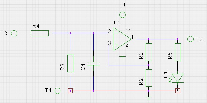
It consists of the following components:
Inverting Schmitt trigger (U1, R1, R2)
I chose an easily available OpAmp LM358N. I chose the inverting configuration to completely isolate input from output. I chose R1 and R2 such that the input threshold voltage would be approx. 50 mV (a very light touch of the probe generates this easily). The threshold voltage is simply the voltage between the voltage divider R1 and R2. I chose R1 = 5k4 and R2 = 55.
V_threshold = Vcc * R2 / (R1 + R2) = 5 * 55 / (5k4 + 55) = 50 mV
Pulldown resistor (R3)
The negative input of the OpAmp and the piezo element on T3 are very high impedance and would float if not pulled down. In addition, the real OpAmp leaks a bit of charge into this terminal, bringing it up to 60mV which is even above the switching threshold. To bring the voltage much closer to 0V, I added a rather strong pull-down resistor R3 = 87k. The piezo has no problems with this load.
Low-pass filter (R4, C4)
In my wiring, T3 will be connected to a long line subject to interference. R4 together with C4 form a simple low-pass filter which a time constant t = 0.24 µs , which is shorter than what will be expected from the signal of the piezo element.
LED (R5, D1)
The LED and its limiting resistor R5 = 480 Ohms (for approx 10mA) is just there for immediate optical feedback.
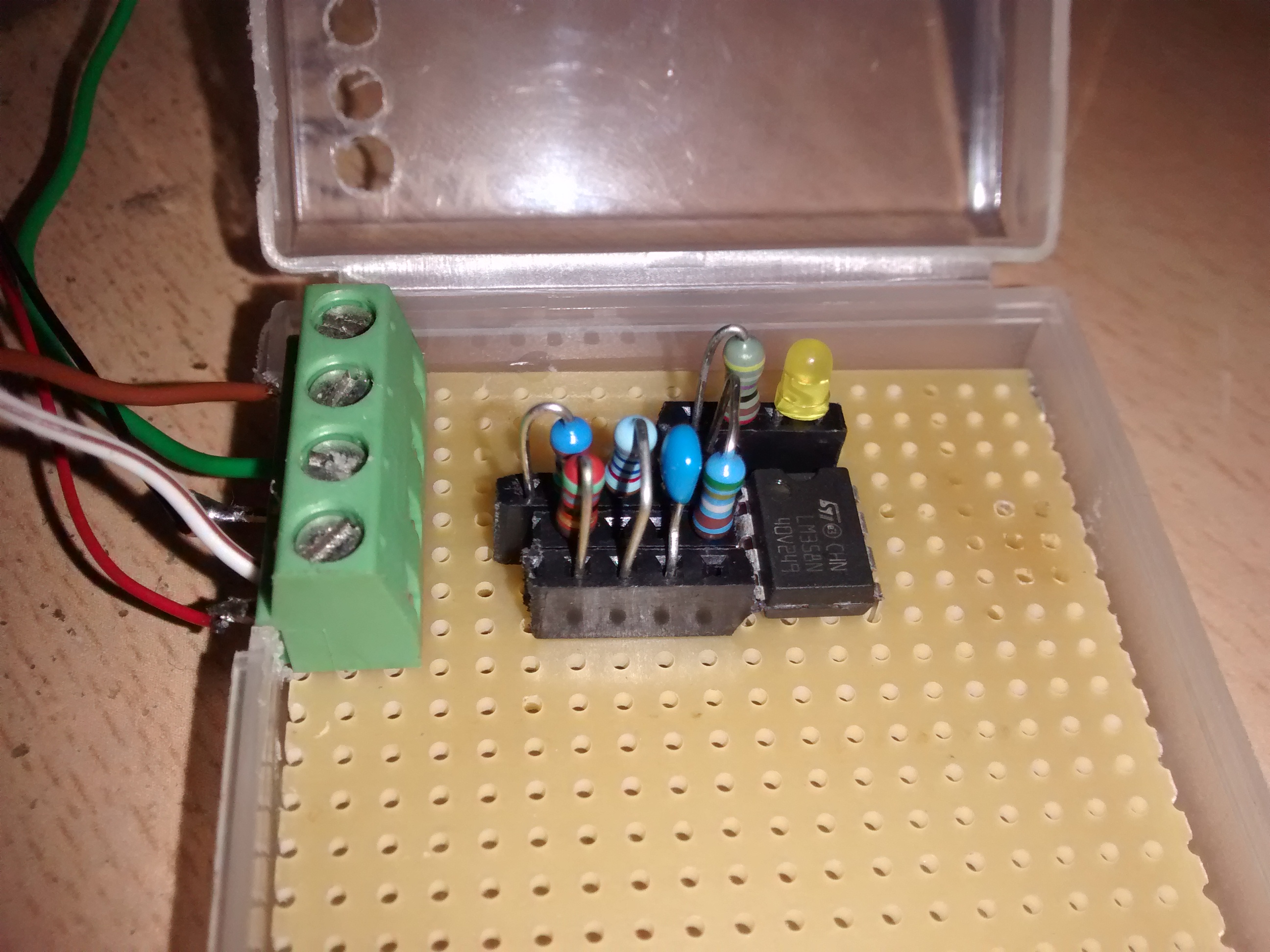
Implementation on a development board
Above schematic can be transferred into the following equivalent simple development wiring layout (C4 is labelled C1):
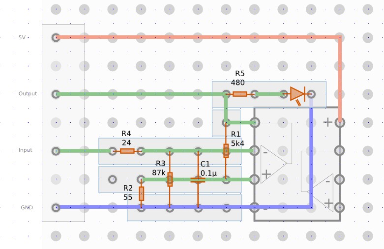
The resistors and capacitors can be easily exchanged for trial-and-error fine-tuning:
Verification using an oscilloscope
The following probes were connected:
Yellow: The input of the piezo element before low-pass filter
Blue: The input of the piezo element after low-pass filter
Pink: The output of the circuit
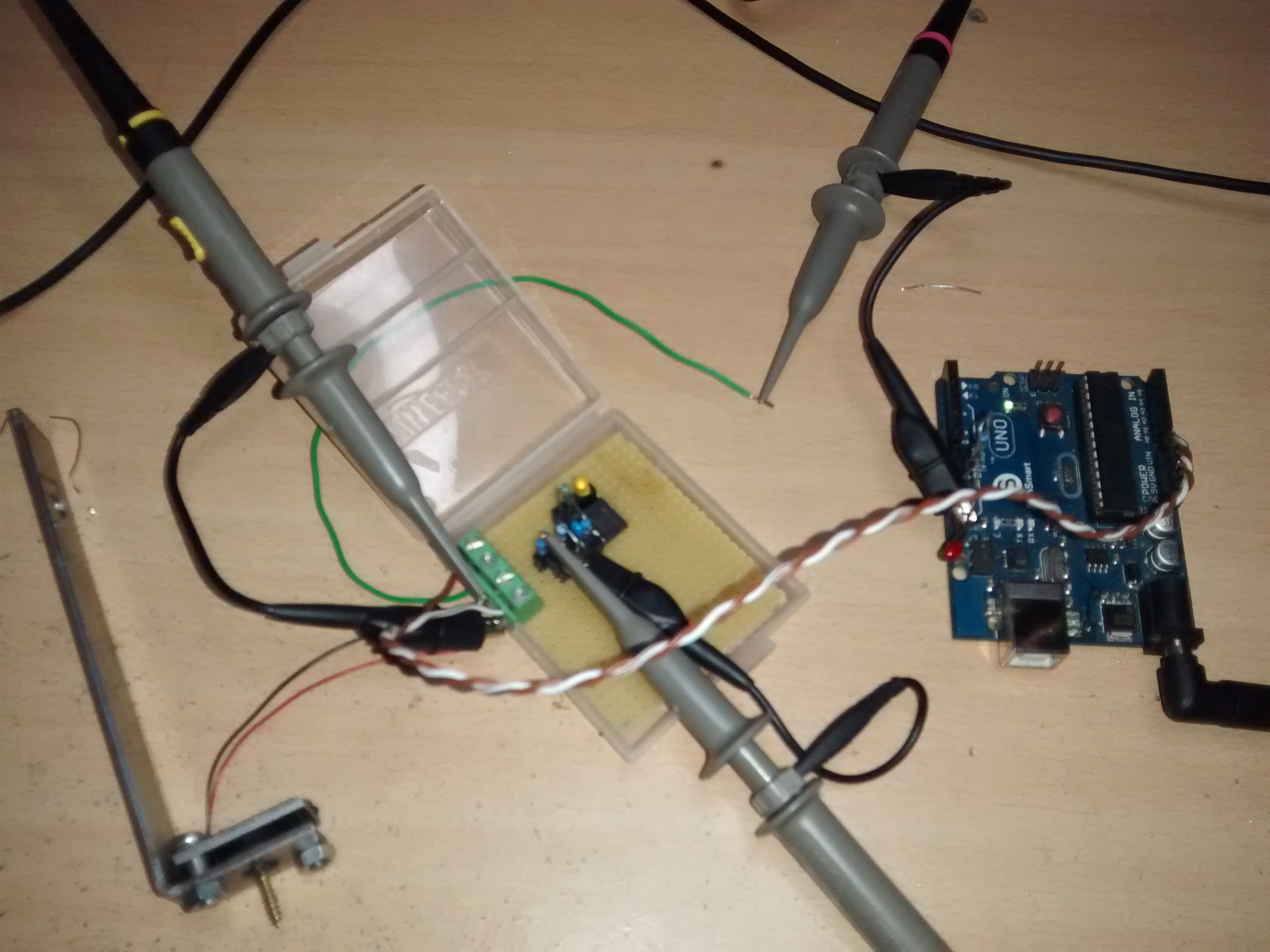
Input voltage without pull down resistor (yellow graph). The OpAmp is leaking some charge into the input terminal, causing the input voltage to raise to about 60mV. Connecting a pull down resistor will rectify this.

Input with pull-down resistor applied. Input voltage is now down to less than 5mV.

Touching the piezo probe increases voltage on the input. At 50mV, the output switches to LOW.

A faster, oscillating signal. When going over 50mV, the output switches to LOW. When going below 0V, the output switches back to HIGH.

An even faster oscillating signal (I hit the probe holder with a screwdriver). The behaviour is as expected.
